Design-time considerations
Workflow overview
In order to make your robot possible to export, you need to follow some conventions. The summary is as follows:
onshape-to-robotexports an assembly of the robot,Be sure this assembly is a top-level assembly, where instances are robot links (they can be parts or sub-assemblies),
The first instance in the assembly list will be considered as the base link,
All the instances in the assembly will become links in the export
Mate connectors should have special names (see below for details):
dof_name: for degrees of freedomframe_name: to create a frame (site in MuJoCo)fix_name: fix two links together, causingonshape-to-robotto merge themclosing_name: to close a kinematic loop (see Handling kinematic loops)Other mates are not considered by
onshape-to-robot
Orphaned links (that are not part of the kinematic chain) will be fixed to the base link, with a warning
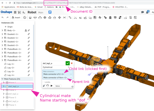
Specifying degrees of freedom
To create a degree of freedom, you should use the dof_ prefix when placing a mate connector.
If the mate connector is cylindrical or revolute, a
revolutejoint will be issuedIf the mate connector is a slider, a
prismaticjoint will be issuedIf the mate connector is fastened, a
fixedjoint will be issued
Note
You can specify joint limits in Onshape, they will be understood and exported
Inverting axis orientation
You sometime might want your robot joint to rotate in the opposite direction than the one in the Onshape assembly.
To that end, use the inv suffix in the mate connector name. For instance, dof_head_pitch_inv will result in a joint named head_pitch having the axis inverted with the one from the Onshape assembly.
Naming links
If you create a mate connector and name it link_something, the link corresponding to the instance
on which it is attached will be named something in the resulting export.
Adding custom frames in your model
You can add your own custom frames (such as the end effector or the tip of a leg) to your model.
In URDF, it will produce a dummy link connected to the parent link with a fixed joint
In SDF, a
frameelement will be addedIn MuJoCo, it will result in a site
To do so, either:
Add a mate connector where you want your frame to be, and name it
frame_something, wheresomethingis the name of your frame
OR
Add any relation between a body representing your frame and the body you want to attach it to. Name this relation
frame_something.

Here is a document that can be used (be sure to turn on “composite parts” when inserting it, use the frame composite part): Onshape frame part
Note
The instance used for frame representation is only here for visualization purpose and is excluded from the robot.
You can however include it by setting draw_frames to true in the config file, mostly for debugging purposes.
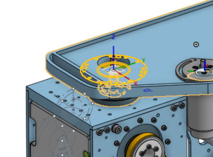
Joint frames
Joint frames are the ones you see in Onshape when you click on the joint in the tree on the left. Thus, they are always revolving around the z axis, or translating along the z axis.
Fixed robot
If you want to export a robot that is fixed to the ground, use the “Fixed” feture of Onshape:

Robot with multiple base links
The robot can have multiple links. In that case, the first instance appearing on the list will be considered as a separate base link.
Note
MuJoCo and SDF both supports multiple base links, while URDF doesn’t.
In that case, you might consider using multiple URDF files, or adding a dummy base link. However, this will fix all the base links to the base link without freedom.
Gear relations
Gear relations are exported by onshape-to-robot. Be sure to click the source joint first, and then the target joint. They will be exported as <mimic> in URDF and SDF formats, and as equality constraints in MuJoCo.
